
Liquid Shim vs. Steel Shim Plates
A Structural Engineer's Comparison
Steel shim stacks are the industry default for levelling column baseplates and bearing seats during installation. Fast to source and familiar to every erector, they do exactly what they’re built for: holding a plate at the correct elevation while the permanent connection is completed.
The question is what happens afterward, once the shims stay in place as the permanent load path. A shim stack carries load through a number of discrete contact points rather than the full baseplate area. Under cyclic load, that’s what drives shims to progressively work and redistribute pressure over time.
DIAMANT MM1018 removes that point-contact condition, bonding to both surfaces as a continuous, fatigue-tested structural layer.
Kubri Engineered Solutions supplies MM1018 and the engineering support to specify it correctly.
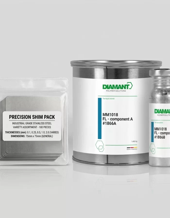
Technical Data
MM1018 Liquid Shim vs. Steel Shim Stacks
The table below compares the verified technical properties of DIAMANT MM1018 against the general engineering characteristics of steel shim stacks used for baseplate and bearing seat levelling.
| Property | MM1018 Liquid Shim (FL) | Steel Shim Stacks |
|---|---|---|
| Load transfer mechanism | Continuous, bonded structural layer across the full contact area | Point/patch contact at a limited number of discrete shim locations around the baseplate perimeter |
| Contact area | 100% void fill; cures bonded to both surfaces | Typically a small fraction of the total baseplate area; shims are commonly positioned only at the plate edges and corners, not across the full footprint |
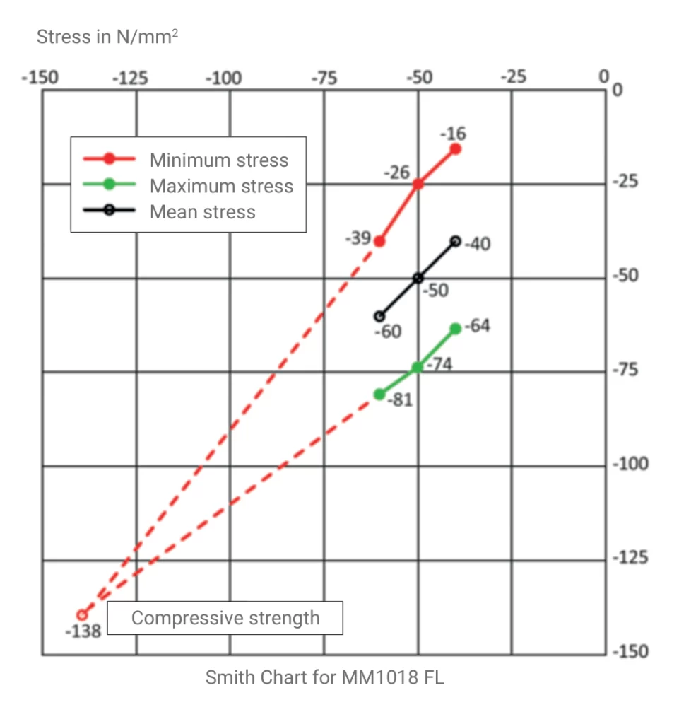
| Behaviour under cyclic/dynamic load | Fatigue-tested to 10 million load cycles at mean stresses of 40-60 N/mm² with no visible damage (ibac RWTH Aachen, test M1999) | No equivalent published third-party fatigue certification identified for steel shim stack systems |
| Long-term stability under vibration | Dimensionally stable; loss of pre-tensioning force ~10% over 50 years (log-extrapolated relaxation test, 2 mm gap, restrained) | Bolted connections under cyclic shear are documented to undergo progressive relaxation and self-loosening in stages, independent of shim quality |
| Installation method | Poured or injected into a sealed cavity; cures in place | Site-fitted: cut, ground, or packed to fill the measured gap during installation; may require field adjustment and re-fitting |
| Installation time to full load | 97% or more of design strength at 24 hours (+21°C); full design strength at 7 days. Service load not to be applied before strength is verified. | Immediate mechanical support at installation, but typically supplemented by grout or left as a permanent point-contact condition |
| Structural approval | abZ Z-3.82-2042, DIBt (Germany): general building authority approval covering use in preloaded structural connections | No equivalent general building authority approval for shim stacks as a permanent load-bearing layer identified |
Load transfer, contact area, fatigue certification, and long-term stability figures for MM1018 are sourced from the official DIAMANT Technical Datasheet (#1866, Version 1.1, dated 14 July 2026). KES can map this data against project-specific design specifications on request.
Steel shim behaviour is described according to established structural engineering practice, including AISC Design Guide 1 (Base Plate and Anchor Rod Design) and AS 4100 (Connections).
Fatigue certification
Why Point Contact Fails
Under Cyclic Load
A steel shim stack transfers the full compressive load of a connection through a small number of discrete bearing points (not the full baseplate area), which concentrates bearing stress well above the nominal design pressure at each point.
Under a static load case, the foundation and baseplate can redistribute that concentrated stress through localised yielding until equilibrium is reached. Under a cyclic case- a wind turbine flange, a bridge bearing under live traffic, a crane rail, or rotating equipment under sustained vibration- those same points are loaded and unloaded repeatedly, with no equivalent redistribution mechanism once the connection is in service.
MM1018 FL was independently fatigue-tested by ibac (Institut für Bauforschung) at RWTH Aachen University: 10 million load cycles at mean stresses of 40, 50, and 60 N/mm², with no loss of structural integrity (EN 1993-1-9 sets the constant-amplitude fatigue limit for structural steel at 5 million cycles). Because it bonds to both surfaces as a continuous layer rather than concentrating load at discrete points, it doesn’t depend on point contact remaining stable over millions of cycles.
On current review of published manufacturer and industry technical literature, KES has not found a steel shim stack system with comparable published third-party fatigue testing at this cycle count. For structural engineers who need a documented basis for a permanent load path under cyclic load, MM1018 is the only material in this category that provides one.
Application guide
When to Specify Which
Standard Scenarios for Steel Shim Stacks
Steel shim stacks remain the correct, practical choice for:
- Temporary works during installation: holding a baseplate or bearing at the correct elevation and alignment before the permanent connection is completed.
- Coarse alignment: Levelling and setting elevation ahead of grouting or final fixing, where the shims are not intended to be the final permanent load path.
- Minor packing during assembly: Small, non-critical adjustments where the load case is static and the connection isn’t subject to sustained vibration or repeated cyclic loading.
High-Demand Scenarios for MM1018 Liquid Shim
MM1018 is specified over steel shim stacks as the permanent load path in the following cases:
- Rotating Equipment Baseplates: Sustained vibration from pumps and rotating machinery makes point-contact shimming unsuitable as the permanent bearing layer. See liquid shim for equipment foundations.
- Bridge Bearings Under Live Traffic: Traffic loading is inherently cyclic, and a bridge bearing seat needs a load path that remains stable for a multi-decade design life. See liquid shim for bridge bearings.
- Wind Turbine Tower Flanges: Cyclic wind and rotor loading make the flange connection fatigue-critical, where a bonded, full-surface layer is required rather than discrete shim points. See liquid shim for wind turbine applications.
- Crane Runway Rails: Every wheel pass loads and unloads the rail seat, making sustained point contact unsuitable over the service life of the rail. See liquid shim for crane runway rails.
- Critical Structural Connections and Preloaded Bolted Joints: Connections that must retain consistent pre-tension over decades benefit from MM1018's documented dimensional stability. See liquid shim for bolted joints.
Frequently Asked Questions
Some specifications call for shims to be removed once the grout has cured and the connection is fully loaded; others leave them permanently encapsulated in the grout. The common approach is to use jack screws or bolts that can be backed off before the anchor bolts are fully torqued.
A well-made, precisely fitted shim only carries load at the small area where it physically sits, leaving the rest of the baseplate unsupported until grout or another fill material takes up the surrounding gap. Upgrading the shim material itself doesn’t change that basic geometry.
Yes. Shims are commonly used for initial coarse alignment and elevation setting during assembly. MM1018 is then poured or injected to fill the remaining gap and establish the permanent, full-surface load path once the structure is correctly positioned. The two methods serve different stages of the same installation process; they are not mutually exclusive.
MM1018 FL reaches 97% or more of design strength at 24 hours (+21°C) and full design strength at 7 days. Service load is not to be applied before strength is verified. A conventional shim-and-grout sequence typically involves fitting and adjusting the shims on site, followed by a separate grouting step with its own cure period. MM1018 is injected directly around the aligned connection, reducing the number of separate installation stages.

Engineering Authority,
Australian Support.
Replacing a steel shim stack with a liquid shim as the permanent load path changes how the connection is detailed, how the interface is sealed and injected, and what documentation is available to demonstrate the load path is sound. Getting these details right on the first installation avoids costly rework later.
Helping you manage that risk is Kubri Engineered Solutions, Australia’s dedicated technical authority for liquid shim technology.
Kubri Engineered Solutions is the Australian partner for DIAMANT Polymer GmbH, manufacturer of MM1018 The Liquid-Shim®, and holds exclusive technical partnerships with globally recognised manufacturers, including Maurer (expansion joints, structural bearings), Panacor (noise barriers, fire protection walls), and EarthTec (reinforced retaining walls).
KES supports your specification by supplying a complete engineering support package:
Design Support:
Interface review and product-variant selection (FL, P, or Smart S) matched to the gap geometry.
Installation Methodology:
Preparation of method statements covering sealing, injection layout, and QA checkpoints.
Interface Control:
Specification of the complete system, including MM1018 SEAL and dedicated injection hardware.
Documentation:
Provision of material certification, batch traceability, and abZ approval documentation formatted for ITPs and asset registers.
Founded by Loai Shokry, a Chartered Professional Engineer (CPEng) with a career spanning the design and delivery of multi-billion-dollar infrastructure projects in Australia and worldwide, Kubri Engineered Solutions is a specification and engineering partner, not just a product distributor.
For a full technical overview of liquid shim technology and applications,
visit the Liquid Shim Australia resource centre.
Talk to a KES engineer
Send us your connection details. A KES engineer will respond within one business day with the correct product selection and the next steps on installation methodology. Final product selection and specification remain subject to engineer-of-record approval for your project.