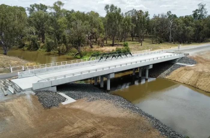
Gardelegen, Germany
Enercon Hybrid Tower
The concrete foundation's tension ring and the steel tower base segment were connected using MM1018 to achieve a force-fit and form-fit connection ahead of turbine commissioning.

Full force-fit and form-fit load transfer across bolted tower flange connections.
Fatigue-tested to 10 million load cycles at ibac RWTH Aachen.
A wind turbine tower flange is one of the most demanding cyclic load connections in structural engineering, subjected to continuous dynamic loading for the full operating life of the turbine.
DIAMANT MM1018 closes the residual gap between flange faces with a full-surface, dimensionally stable layer, tested to 10 million load cycles.
Kubri Engineered Solutions is the Australian technical partner for DIAMANT Polymer GmbH, supplying and specifying MM1018 for onshore and offshore wind tower connections as Australia’s wind energy pipeline expands.
A wind turbine tower flange connection is designed to carry load evenly across its full bolted circumference. Under Eurocode EN 1993-1-9, the constant-amplitude fatigue limit for a welded steel connection is set at 5 million cycles, a threshold a turbine tower flange exceeds many times over across a 20-25 year service life of continuous dynamic loading.
Manufacturing tolerance means the flange faces are not in perfect, uniform contact when segments are bolted together. Transport handling and the sheer scale of tower segments and foundation rings contribute to a residual gap at the flange interface.
Left unaddressed, that gap concentrates load at isolated points of contact instead of distributing it across the full flange face. This condition accelerates fatigue crack initiation in a connection that is already carrying one of the most demanding cyclic load profiles in structural engineering.
Flange gap size and distribution directly affect bolt load and fatigue performance, with larger or unevenly distributed gaps increasing the stress range individual bolts experience under cyclic loading. Flange fatigue performance depends as much on how completely the faces bear on each other as it does on bolt grade or torque.
By closing that residual gap completely, MM1018 removes the uneven bearing condition responsible for elevated bolt stress ranges under cyclic load, and restores the full-circumference load path the connection was designed for.
MM1018 FL or P is poured, injected, or trowelled into the sealed gap between tower flange faces, or hybrid tower segment interfaces. It flows into or is applied across the space present on site and cures into a rigid, dimensionally stable layer that restores full-surface, force-fit and form-fit contact, in a four-step sequence carried out on site:
01
The gap perimeter is sealed with MM1018 Seal, pressed in to a minimum depth of 10mm for a leak-proof barrier, then left to cure before injection begins.
02
MM1018 FL is poured or injected from the lowest point of the gap, or MM1018 P is applied by trowel on vertical or overhead flange faces, with injection and ventilation points planned so trapped air is displaced ahead of the material.
03
The material cures with negligible shrinkage (0.035%) and reaches ≥97% of design strength at 24 hours (+21°C) with full design strength at 7 days. Service load is not to be applied before strength is verified.
04
Sample sets are taken during the pour and checked for Shore D hardness and cure consistency before the flange connection is bolted to final torque and the tower segment is loaded.
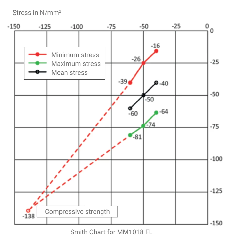
MM1018 FL has been fatigue-tested to 10 million load cycles and has passed. Testing was carried out independently by ibac at RWTH Aachen (test M1999) at mean stresses of 40, 50, and 60 N/mm²; all three test series completed the full 10 million cycles with no loss of structural integrity. For context, EN 1993-1-9 sets the constant-amplitude fatigue limit for structural steel at 5 million cycles.
To KES’s knowledge, no other polymer gap-compensation material marketed in Australia currently carries a published third-party fatigue credential of this duration.
MM1018 FL holds German general building authority approval (abZ Z-3.82-2042) from DIBt. It achieves a compressive strength of 161 N/mm² under DIN EN 12190:1998.
| Property | Value |
|---|---|
| Fatigue strength | 10,000,000 load cycles at mean stresses of 40, 50, and 60 N/mm² (ibac RWTH Aachen, test M1999). No loss of structural integrity recorded |
| Compressive strength (fully cured) |
161 N/mm² (DIN EN 12190:1998) |
| Curing time to full load capacity | 97% or more of design strength at 24 hours (+21°C); full design strength at 7 days. Service load not to be applied before strength is verified. |
| Curing at other temperatures | Min. curing temperature +5°C; accelerated curing permitted to a maximum of 50°C. Strength development varies with temperature. Refer to DIAMANT TDS #1866 V1.1 for values by temperature and age. |
| Maximum layer thickness (manufacturer-tested) |
Up to 140 mm |
| Maximum layer thickness (abZ-approved) |
Up to 10 mm per layer |
| Service temperature (per abZ) |
-20°C to +50°C |
| Shrinkage | 0.035% (DIN EN 12617-4:2002) |
| Product variants for this application | MM1018 FL (poured/injected, horizontal flange gaps) and MM1018 P (trowel-applied, vertical or overhead flange faces) |
| Key accessories | MM1018 Seal (perimeter sealing), injection/ventilation packers, DIAMANT cleaner, screw protection for flange bolts where applicable |
The compressive strength, shrinkage, and fatigue data figures for MM1018 are sourced from the official DIAMANT Technical Datasheet (#1866, Version 1.1, dated 14 July 2026).
KES can map this data against project-specific tower design specifications on request.
Gardelegen, Germany
The concrete foundation's tension ring and the steel tower base segment were connected using MM1018 to achieve a force-fit and form-fit connection ahead of turbine commissioning.

Luhanka, Finland
MM1018 was applied between the tower base flange and concrete pedestal to achieve a full-area compressive interface, replacing the discrete point contact of a conventional shim stack.
For a full technical overview of liquid shim technology and applications,
visit the Liquid Shim in Australia resource centre.


Kubri Engineered Solutions is Australia’s dedicated technical authority for liquid shim technology and the Australian partner for DIAMANT Polymer GmbH, manufacturer of MM1018 The Liquid-Shim®.
KES supports every specification with a complete engineering support package:
Design Support:
Engineering review of the tower flange or foundation ring interface during the design phase, before tower segments are fabricated or transported.
Installation Methodology:
Project-specific method statements, ITP hold points, and on-site attendance for first-of-type tower connection installations.
Interface Control:
Product selection across the MM1018 family (FL, P, Smart S, Seal) matched to gap geometry, access, and project constraints.
Documentation:
Material certification, batch traceability, abZ approval documentation, and installation records formatted for ITP, handover, and the asset register.
Founded by Loai Shokry, a Chartered Professional Engineer (CPEng) with a career spanning the design and delivery of multi-billion-dollar infrastructure projects in Australia and worldwide, Kubri Engineered Solutions operates as a specification and engineering partner across the full project lifecycle, from design review to handover documentation.
Final product selection and specification remain subject to engineer-of-record approval for your project.
Yes. MM1018 P is a trowel-applied, paste-consistency variant formulated to remain stable on vertical and overhead surfaces without slumping, making it suitable for tower flange faces that aren’t horizontal.
DIAMANT recommends grid-blasting to a roughness of 50-60 µm (SA2.5) where practical, and cleaning the surface free of oil, corrosion products, and dust with DIAMANT cleaner or equivalent beforehand.
MM1018 is rated for seawater exposure and is corrosion- and weather-resistant. Project-specific environmental exposure should be confirmed with a KES engineer during design review.